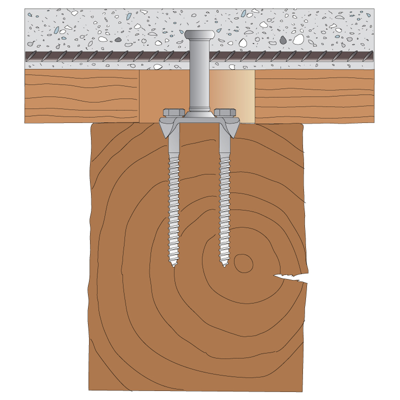
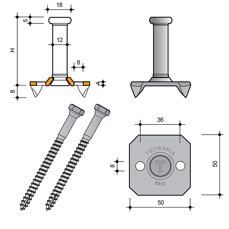
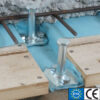
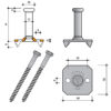
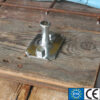
CONNECTOR COMPOSITION
A 12 mm headed stud
A 4 mm thick 50×50 square pressed base plate with folded corners to create crampons. The stud connector and the base plate are cold riveted together.
Two 8 mm coach screws going through the two holes of the plate.
Galvanised steel screws with sharp Ø 8.0 mm tip, length 70, 100 and 120 mm. All the connector components are zinc plated with an average protection thickness of 8 μm, corresponding to 2 cycles of “Kesternich” corrosion resistance.
| CODE |
HEIGHT |
SCREWS * |
| CTLB020 |
20 mm |
8 X 100 mm |
| CTLB030 |
30 mm |
8 X 100 mm |
| CTLB040 |
40 mm |
8 X 100 mm |
| CTLB060 |
60 mm |
8 X 100 mm |
| CTLB070 |
70 mm |
8 X 100 mm |
| CTLB080 |
80 mm |
8 X 100 mm |
| CTLB105 |
105 mm |
8 X 100 mm |
| CTLB125 |
125 mm |
8 X 100 mm |
| CTLB150 |
150 mm |
8 X 100 mm |
| CTLB175 |
175 mm |
8 X 100 mm |
| CTLB200 |
200 mm |
8 X 100 mm |
* CTL BASE wood-concrete connectors are also available with 8 x 70 mm and 8 x 120 mm screws
Caratteristiche meccaniche agli stati limite del connettore CTL MAXI al variare dello spessore del tavolato e classe del legno
Tavolato
(cm) |
Legno
(classe minima) |
Resistenza caratteristica
Fv,Rk (kN) |
Modulo di scorrimento allo
stato limite di servizio Kser (kN/mm) |
Modulo di scorrimento allo
stato limite ultimo Ku (kN/mm) |
| 0 |
C16, GL24 |
19,30 |
18,60 |
10,40 |
| 0 |
D30 |
24,50 |
21,20 |
13,60 |
| 2 |
C16, GL24, D30 |
15,00 |
7,68 |
4,35 |
| 4 |
C16, GL24, D30 |
11,30 |
3,06 |
2,66 |
- Valori caratteristici del connettore CTL MAXI per eseguire un calcolo secondo il metodo degli Stati Limite Ultimi Download (formato pdf)
- E’ possibile eseguire il calcolo dei connettori CTL MAXI utilizzando il software gratuito scaricabile nella sezione Download
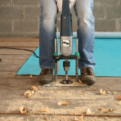
VIDEO
Fasi di posa di un connettore Maxi sopra assito.
Posa di un connettore Maxi senza preforo
DOCUMENTI
Posa connettore Maxi
 CT L POSA MAXI IT
 CT L CATALOGO IT
 CT L SCHEDA MAXI IT
 CT L CTL CERTIFICAZIONE AVIS TECHNIQUE IT
 CT L CTL CERTIFICAZIONE ETA EN
 CT L CTL DOP IT EN